 Power
objects in your design show where power is connected into your
circuit. Various shapes of power symbols are defined.
Power
objects in your design show where power is connected into your
circuit. Various shapes of power symbols are defined.Advanced drawing techniques
For the more advanced schematics, TinyCAD has more advanced features.
No Connects
Normally all of the pins on a symbol must be connected. There may be times when you wish to leave a pin unconnected but wish to show that you haven't forgotten the pin and it is intentionally left unconnected.
If you do not wish to connect to a certain pin then use the no-connect option on the Toolbar. Place a no-connect on every pin that is not to be connected to anything else.
Any unconnected pins can be found by using the the Design Rules Checker in the Special menu.
Adding Power
 Power
objects in your design show where power is connected into your
circuit. Various shapes of power symbols are defined.
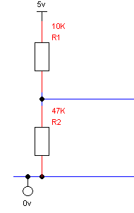
You must always make the connection to power at the end of the power object's pin. A junction may be necessary if the connection is to the centre of a wire or where wires cross. If a junction is necessary it will be placed automatically for you.
The shape of the power object is ignored - it is the value of the power item which is important. All items connected to power objects of the same value are considered connected together.
Some component symbols, such as the 74 TTL library symbols, are automatically connected to power. To ensure the power is correctly connected, always use the same power names that are used in the library. For example, when using the 74 TTL library use the power names GND and VCC for 0v and 5v respectively.
Using Labels
Labels enable you to make connection between points on your design which are some way apart. They are also useful for when many connections are required to the same point.
|
|
|
|---|---|
|
Correct use of labels |
|
A label should be placed above or alongside a wire. The label is considered connected at the bottom left hand corner of the label when the label is horizontal (Right) and the bottom right hand corner when the label is vertical (Up). A small red rectangle shows where the label is connected to.
All wires with the same label name will be considered connected together. This way a connection between the wires is formed without you having to actually draw it.
Adding Buses
 Buses
can be used to indicate a large number of connections. To help you
draw a bus the repeat options are present.
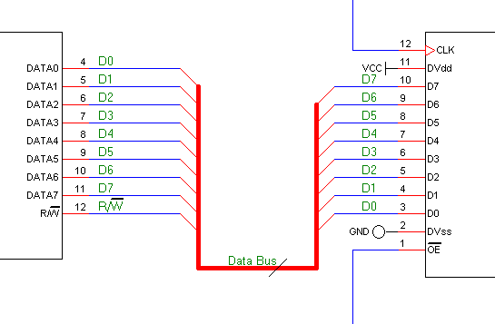
To create a bus, first draw the bus near where you wish to connect it. Now add a bus entry to the bus. Press 'R' (for repeat in the Edit Menu) to repeat this as necessary for the number of entries you wish to make.
Draw a wire from the bus entry to the connection point. Now press 'R' again, to complete all the wire connections.
Finally you must add the labels. Place the first label. Depending on your repeat options the label name will be updated automatically. Place a label over each wire.
Now the bus connection is complete!
Use the same names for the bus entries on all connections to bus; however, the order of the names is unimportant. Buses do not require junctions anywhere on them.
Once a bus is in place, you may name the bus using the Bus Name tool. You may use this to place some text next to the bus. The name can indicate how many conductors the bus represents, by specifying just a single number, or it may qualify what the bus is for example by calling it "Data Bus" etc.